Published UV Papers
UV Publications
UV Publications
UV Publications

General Overview
Industrial sources of ultraviolet (UV) energy have long included medium pressure mercury arc (electrode) and microwave powered lamps as well as spot cure systems. More recently light emitting diodes (LEDs) have entered the picture. All four technologies are used to crosslink inks, coatings, and adhesives in a wide range of manufacturing processes.
Both arc and microwave curing technology rely on the vaporization of a small amount of mercury within a sealed quartz tube containing an inert gas mixture. The physics of mercury result in the silvery-white metal emitting ultraviolet light when vaporized into a high temperature plasma gas. Electrodeless lamps employ microwaves to vaporize the mercury; whereas, electrode lamps harness a high voltage arc struck between two tungsten electrodes to achieve the same result.
When mercury is vaporized into a plasma gas, it emits a defined spectral output across ultraviolet, visible, and infrared bands. Approximately 1/3 of the total output is UV. 1/3 is visible, and 1/3 is infrared. The UV output includes UVA, UVB, UVC, and UVV. For these reasons, both arc and microwave lamps are considered broadband or broadspectrum. The standard mercury UV spectral output can be altered slightly by adding small amounts of metal such as iron, gallium, lead, tin, or indium to the inside of the quartz tube. Lamps with added metals are typically referred to as doped, additive, or metal halide. Most ink, adhesive, and coating formulations are predominantly designed to match the output of either standard mercury (HG) or iron (FE) doped lamps. White inks and coatings containing titanium dioxide generally cure better with gallium (GA) doped lamps.
Both UV equipment suppliers and lamp (bulb) manufacturers provide spectral output graphs for the various products they offer. These charts plot irradiance (intensity) on the y-axis against wavelength on the x-axis. The irradiance can be displayed in several ways including measured output (W/cm2), relative output (unitless), and normalized output (percentage). Relative output depicts the portion of UV irradiance at a given wavelength or band of wavelengths with respect to the entire output. Normalized output sets the greatest output value to 100% with other peaks in irradiance shown as a relative percentage of the maximum. The following three spectral output graphs show relative irradiance with respect to wavelength for a mercury arc lamp, an iron arc lamp, and a gallium arc lamp. These graphs are courtesy of Baldwin Technologies.


Unlike medium pressure mercury lamps, UV LEDs are solid state semiconductors. They contain no moving parts, quartz tubes, or mercury plasma gas and operate at temperatures that are often less than a 1/10th of the operating quartz surface temperature of conventional lamps. When connected to a DC power source, an electric current flows through the semiconductors. As electrons flow from the negative to positive side of each discrete LED, the electrons drop into a state of lower energy. The energy differential is released from the device in the form of ultraviolet photons spread over a relatively monochromatic spectral distribution.
The material structure of the LED determines the wavelength distribution with commercially available peaks occurring at 365, 385, 395, and 405 nm. The three longer wavelengths (385, 395, and 405 nm) are all built on a gallium nitride foundation and are fabricated simultaneously on the same production lines. 365 nm LEDs, however, contain aluminum in the substrate foundation and must be fabricated separately. 365 nm LEDs lag the longer wavelengths in development and currently emit approximately 20% less total UV output. Development of UV LEDs is a matter of material science and production capabilities. The LEDs are measured after fabrication and typically binned +/- 5 nm from the nominal specification. The following image illustrates the relatively monochromatic, narrow bell-curve shaped nature (not broadspectrum) of UV LEDs.

UV LED technology is experiencing steady market adoption in longer UVA wavelengths (365, 385, 395, and 405 nm). While still years away from commercial viability, there is ongoing development work in shorter UVB and UVC bands. 280 nm is currently the most promising UVB/UVC peak. There is no UV LED source that directly mimics a conventional boradspectrum lamp, but longer wavelengths emitted by LEDs result in their spectral distribution being more similar to the upper portion of iron or gallium lamps which also emit some output in the 385 to 405 nm range. Both UV LEDs and iron and gallium doped lamps utilize longer (near visible) wavelengths to penetrate deeper into the chemistry and produce better through cure particularly with thicker, opaque, and pigmented formulations.
For UV LED clear coatings, achieving a hard, scratch resistant surface cure without yellowing has been the primary challenge. This is because many coating formulations rely on shorter wavelengths emitted by broadband lamps for sufficient crosslinking at the surface. Photoinitiators designed to react to the longer wavelengths emitted by UV LEDs tend to yellow slightly during exposure. Current UVB and UVC LEDs do not yet satisfy output, cost, reliability, and life requirements and lag development compared to UVA. Nevertheless, higher UVA irradiances and adjustments to the formulations have often been found to resolve surface cure and yellowing issues for LED formulated graphics coatings; however, these coatings tend to cure at slower press speeds than both high speed conventional mercury coatings and high speed LED formulated inks. For other more challenging formulations such as functional and industrial coatings, ongoing development work is attempting to close the gap.
Both microwave and arc lamps are widely used in today’s manufacturing processes and have been for decades. By comparison, UV LED lamps represent a much smaller but growing portion of the installed base with the very first devices appearing on the market in the early 2000s. For many years, UV LED curing systems were of relatively low power and had limited commercial use. But after more than 15 years of continued advancements in the areas of power output, efficiency, reliability, operation, life, integration, formulation, and production economics, the technology is being utilized across an ever growing list of applications. The exciting evolution of UV LED technology continues and presents numerous opportunities for manufacturing processes that currently use conventional UV sources, applications that have never adopted the technology, and brand new or yet to be developed applications.
Conventional arc lamps typically emit in the range of 1 to 3 Watts/cm2 at the focus, and microwave lamps generally emit as much as 5 Watts/cm2 at the focus. While it varies by system, the focus is typically 50 mm (2") from the surface of the lamp head. Today's commercial UV LED curing systems can emit up to 20 Watts/cm2 at the emitting window for air-cooled heads and, in some cases, up to 50 Watts/cm2 at the emitting window for liquid-cooled heads. Unlike conventional lamps, UV LED systems do not have a focus, and there is no generally accepted industry standard reference location for reporting LED irradiance. Some suppliers specify near the diodes or at the emitting window while others report irradiance at an offset distance from the window or encapsulated modules. While peak irradiance is important for crosslinking, an increasingly higher irradiance is not always advantageous and can even work against the physics of crosslinking. Wavelength and energy density also play critical roles and should be considered during source selection.
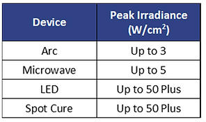
Spot cure systems include light guides, area (flood) cures, and portable, handheld units. They can be either bulb based or LED based. Many low-power LED versions are designed such that the emitter, power, and controls are all tightly contained in a single hand held device. These compact, low-powered systems are relatively inexpensive and readily available for purchase at brick-and-mortar retail stores and through both industrial and online distribution channels. Alternatively, the power and controls for more robust industrial spot cure systems can be located remotely with the UV output channeled through liquid or fiber optic light guides to the desired cure location. In general, spot cure UV systems are available in a wide range of irradiance levels up to 50 Watts/cm2 and come in various form factors. In comparison to most microwave, arc, and LED systems, spot cure systems emit less total energy density (Joules/cm2) even at higher irradiance levels. Spot cure system rely solely on a longer exposure time to generate greater levels of energy density. It should be noted that spot cure systems were the first UV curing source to successfully adopt and commercially deploy LEDs.
Unlike conventional arc, microwave, and high powered LED systems which are typically used in dynamic industrial installations and span lengths from 75 millimeters to upwards of 2 meters, spot cure systems are mostly meant for small area, static installations. That said, area cure systems are sometimes grouped together in multiples to span wider areas and integrate into moving lines such as flat bend conveyors or slower moving webs and sheets. As previously stated, spot cure systems build energy density (Joules/cm2) at the cure surface through longer static or slow dynamic exposure times.
The power required to drive spot cure systems is significantly less than industrial arc, microwave, and LED systems. When comparing the output of spot cure systems to microwave, arc, and LED systems, it is misleading to only consider the irradiance. A better understanding of output can be garnered by comparing the wattage of the supply lamp or supply power for the spot cure system to the supply power of the other systems. Spot cure systems will be less than a few hundred watts per device compared to several thousand watts for the others. Microwave, arc, and LED, systems are generally intended for very different applications than spot cure systems. The spectral output, irradiance, energy density, form factor, and price point should all be considered and matched to the needs of each application.
Lamp Life
While bulb is the most commonly used term to refer to the quartz tube in North America, Europeans are more accustomed to using the term lamp. To Europeans, bulbs are planted in the ground to grow flowers and are not used in curing technology. Throughout this website, the terms bulb and lamp are used interchangeably or often together for clarity.
With respect to lamp (bub) life, arc lamps generally last between 500 and 2,000 hours while microwave lamps fall in the 5,000 to 8,000-hour range. In both cases, lamp life is not an absolute as UV output gradually decreases over time and is impacted by various factors. The design and quality of the lamp as well as the operating condition of the UV system and the reactivity of the formulation matter. Properly designed UV systems ensure that the correct power and cooling required by the specific lamp (bulb) design is provided.
OEM supplied lamps (bulbs) typically provide the longest life. Secondary sources have generally reverse engineered the lamp from an OEM sample, and the copies may not contain the same end fitting, quartz diameter, mercury content, or gas mixture which can all affect the UV output and heat generation. When heat generation is not balanced against system cooling, the lamp suffers in both output and life. Bulbs that run cooler emit less UV. Bulbs that run hotter do not last as long and will warp at quartz surface temperatures exceeding 1,200 degrees C.
The life of electrode arc lamps is limited by the bulb's operating temperature, the number of run hours, and the number of bulb starts. Each time a bulb is struck with a high voltage arc during start-up, a bit of the tungsten electrode wears away. Eventually, the bulb will not re-strike. Many electrode arc lamps incorporate shutter mechanisms which, when engaged, block UV output as an alternative to repeatedly turning the lamp OFF and ultimately limiting the number of starts. By contrast, the life of microwave lamps is only limited by the bulb operating temperature and the number of hours. Microwave lamps are not affected by the number of starts and generally outlast the life of electrode arc lamps. In either case, the formulation also matters. More reactive inks, coatings, and adhesives may result in longer lamp life; whereas, less reactive formulations may require more frequent bulb changes.
UV LED systems are inherently longer lasting than conventional lamps, but UV LED life is also not an absolute. As with conventional lamps, UV LEDs have limits in how hard they can be driven and generally must operate with junction temperatures below 110 degrees C. Over-driving LEDs and under-cooling LEDs will compromise life resulting in more rapid degradation or catastrophic failure. Not all UV LED system suppliers currently offer designs that meet the highest established lifetimes in excess of 20,000 hours. The better designed and maintained systems will last beyond 20,000 hours, and the inferior systems will fail within much shorter windows. The good news is that LED systems across all suppliers are quickly improving and lasting longer each year.
The greatest UV output in both conventional and UV LED systems occurs when systems are brand new. Electrode, microwave, and LED systems all degrade over time; however, the degradation period for properly engineered LEDs is significantly longer and much more gradual. Regardless of which system is being used, it is important to understand the process window for each application and periodically monitor UV output including irradiance and energy density. Wavelength is not generally monitored in the field. Refer to Measurement for more information.
Ozone
Ozone (O3) is an inorganic molecule produced when atmospheric oxygen is exposed to shorter wavelengths between 100 and 240 nm. Broadband sources emit UVC between 200 and 280 nm which overlaps part of the ozone generating region. The decomposition or separation of molecules by the action of light is a naturally occurring phenomena called photolysis. When shorter UVC wavelengths impact oxygen molecules (O2), they cause the oxygen molecules (O2) to split into two oxygen atoms (O). The free oxygen atoms (O) then collide with other oxygen molecules (O2) to form ozone (O3). Since trioxygen (O3) is less stable at ground level than dioxygen (O2), ozone readily reverts back to an oxygen molecule (O2) and an oxygen atom (O) as it drifts through atmospheric air. The oxygen atoms (O) then recombine with one another to once again become molecules (O2). The process is illustrated in the following graphic.

Ozone created by mercury curing lamps is unstable and not a significant environmental concern, but it is necessary that it be removed from the immediate area surrounding workers as it is a respiratory irritant and toxic at high levels. Ozone is heavier than air and will always drift to the lowest possible level. It is a colorless gas with a strikingly sweet and pungent odor. It is often described as a smell similar to metal, a burning wire, chlorine, and an electrical spark. It is the distinct odor surrounding a lightening storm and is most noticeable when broadspectrum UV curing systems are first turned ON. Human olfactory senses can detect ozone as low as 0.01 to 0.03 parts per million (ppm).
While it varies by person and activity level, concentrations greater than 0.4 ppm can lead to adverse respiratory effects and headaches. Proper ventilation is needed to prevent worker overexposure. In general, ozone can cause shortness of breath, wheezing, asthma, pneumonia, and bronchitis symptoms, as well as irritation and damage to airways. Some workers, particularly those who already experience respiratory problems and those performing strenuous manual labor, are more susceptible. As a result, ozone from UV systems should always be ducted away from worker areas.
-
The Occupational Health and Safety Administration (OSHA) and the National Institute of Occupational Safety and Health (NIOSH) recommend a threshold limit of 0.1 parts per million (ppm) or 0.2 mg/m3 not be exceeded.
-
The Environmental Protection Agency's National Ambient Air Quality Standard for ozone is a maximum 8-hour average outdoor concentration of 0.07 parts per million (ppm) or 0.14 mg/m3.
Since ozone creation occurs with the presence of air and UV wavelengths between 100 and 240 nm, greater concentrations of both will result in more ozone generation. This is why larger industrial UV systems with longer more powerful, multi-bank lamps cooled with high volume blowers are designed to contain the exhaust air as it leaves the lamp heads so it can be ducted away from operators. The exhaust should be directed to the upper ceiling of facilities with high roof structures and more preferably outside the building. Since ozone is unstable at the earth's surface, once the exhaust drifts down to ground level, the ozone has typically reverted back to breathable oxygen and is generally no longer a personal safety issue.
Alternatively, lower powered spot cure systems as well as lower powered mercury arc lamps commonly used on early generations of digital inkjet printers (most now use UV LED) often do not require exhaust because the UV output is low and air flow across the lamps is insufficient to generate much ozone. Some installations also use ozone free lamps (bulbs) that have a coating applied to the quartz to block the ozone generating wavelengths. Other installations wanting to avoid ducting or cutting holes in the roof will employ carbon filters on the exit of the blowers. Carbon is effective at reverting ozone back to breathable oxygen. To ensure proper integration and safety, always consult with the original equipment supplier (OEM) on the ozone generation of its products.
Since commercial UV LEDs currently emit between 365 and 405 nm, which is well above 240 nm, ozone is not a factor. Since shorter wavelength UVC LEDs are still in development, it is not yet known whether the wavelength, power, and airflow combinations required for industrial cure and cooling will be significant enough to produce ozone at levels that will require exhaust. They may or may not. We will have to wait and see.
Electrode Arc Lamp Systems
Of the four types of UV systems, electrode arc lamps were the first to be used commercially. Sun Chemical's earliest UV patents for curing with arc lamps date back to the 1940s. Arc lamp designs are the most straightforward with a base system consisting of a lamp (bulb), a reflector, a sheet metal or plastic housing, air or liquid cooling, a shutter assembly, and a power supply. UV system suppliers either design these items internally or source key individual components from an established supplier network. There are a wide variety of electrode arc lamp systems available for purchase from a long list of global suppliers. Some OEM machine builders even make the strategic decision to design and manufacture their own arc lamp systems for use exclusively on their machines.
Electrode lamps are typically designed to the specific needs of a given application or to fit a particular type of machine. As a result, most UV system suppliers tend to limit their focus to one, two, and sometimes three key markets. The UV output, form factor, and features of the systems are designed specifically for a given market or similar market categories.
While basic arc lamp designs are straightforward, that does not mean that all designs are equivalent. Many established system suppliers have spent decades optimizing their unique designs and features, customizing them to meet the needs of their specific customer base and chosen applications. These higher end systems are often very sophisticated and incorporate sleek housing designs, reflectors optimized for greater UV reflectance and reduced infrared, quiet integral shutter mechanisms, web skirts and slots, clam shell web feeding, nitrogen inertion, touch screen operator interface, solid state power supplies, and greater operational efficiencies.
Electrode arc lamps are based around a sealed quartz tube with electrical end fittings. The quartz purity, quartz diameter, type of end fitting, and gas mixture vary across suppliers. See illustration for a typical representation. Unlike microwave systems, electrode systems do not emit UV across the entire housing and, therefore, cannot be scaled with other arc lamps mounted end-to-end to achieve longer lengths. The UV output from arc lamps is reduced near the electrodes and is negligible at the end fittings. As a result, suppliers often note the arc length as the distance between electrodes and the effective cure length as a slightly shorter length of evenly distributed UV output. Arc lamps are typically selected such that the arc length is longer then the desired cure length by 12 mm (0.5 inches) to 50 mm (2 inches). The wider the application, the greater the additional length compensation required.

When electrode lamps (bubs) are powered, the quartz surface temperature is in the neighborhood of 900 degrees C, and a large portion of the radiated output includes significant infrared energy. Forced air is the primary means of maintaining the correct quartz operating temperature. This air can be supplied either negatively (air is pulled through the housing and exhausted out of the assembly and away from the machine or cure surface) or positively (air is pushed through the housing and exhausted either in the direction of the cure surface or out the sides of the housing). Shorter arc lamps (< 330 mm or 13") are more commonly positively cooled, and longer arc lamps (>330 mm or 13") employ negative cooling. Some systems will also incorporate liquid cooling to remove heat from the metal housing, reflector, and integral shutter. Further yet, some systems are liquid filtered which consists of a quartz tube placed between the lamp (bulb) and the cure surface. Distilled water is circulated through the quartz filter to absorb and remove unwanted infrared energy while allowing the UV rays to pass through to the substrate. In general, electrode arc lamps are broadspectrum, emitting UVC, UVB, UVA, UVV, and infrared. Most, but not all, generate ozone at levels that require exhaust.
Microwave Systems
Three companies supply microwave UV curing systems to the global curing industry: Heraeus, Nordson UV, and Miltec UV. Fusion UV developed the technology in the 1970s. Fusion is now owned by German based Heraeus. Two other US based suppliers, Nordson Corporation and Miltec UV, began offering microwave curing products a few decades later. All three actively supply solutions today.
Several of the distinguishing factors of microwave lamp technology include the following:
- A smaller diameter lamp (bulb) is used in microwave lamp heads. The result is a sharper focus and a higher irradiance when compared to similarly powered arc lamps. Microwave bulbs are also slightly necked at the center to more evenly distribute the mercury and improve uniformity of output.
- The UV output effectively spans the entire width of the lamp head. This is due to the lack of electrodes and bulb end fittings.
-
Lamp heads are supplied in 150 mm (6") and 240 mm (10") widths only.
-
Longer curing lengths (widths) are achieved by mating 150 mm (6") and 254 mm (10") width heads end-to-end.
-
Due to the engineering complexity in the microwave cavity, the lamp head design is not typically customized to different applications. Instead the standard 6" an 10" offerings are scaled, paired with accessories, and integrated into a wide range of industrial applications.
-
Configurable systems include a limited number of components that make it easy for microwaves installations to scale to the various widths of industrial manufacturing lines.
-
High pressure and high volume cooling fans (industrial blowers) are either mounted integral to the lamp head or remotely and connected to the lamp head with ducting. Air-flow is positively directed through the lamp head in the direction of UV output. The air is used to cool the housing, magnetrons, reflector, and lamp (bulb).
-
While microwave curing lamps can be used in printing applications, they are more generally employed in industrial coating applications.
Microwave curing systems contain magnetrons inside the lamp head. Magnetrons generate microwaves that are guided toward a sealed quartz tube containing mercury and an inert gas mixture. The microwaves vaporize the mercury into a high temperature plasma gas which emits UV output. Microwave systems are sometimes referred to as electrodeless lamps as there are no wires or electrodes at the end of the lamp (bulb). A wire mesh screen is positioned at the output of the lamp head. It's purpose is to contain the microwaves inside the cavity. An RF (radio frequency) detector must be interlocked and located in close proximity to the microwave lamp head(s). The RF detector is an operator safety feature which monitors microwave energy external to the lamp head and shuts off the units when levels exceed recommended limits. In general, microwave curing systems are broadspectrum emitting UVC, UVB, UVA, UVV, visible, and infrared energy. Microwave lamps use higher volumes of air via blowers for cooling and generate ozone at levels that require exhaust. The following line drawing illustrates the internal components. The microwave UV system photo is courtesy of Heraeus.


Fusion UV developed a letter-based nomenclature to distinguish lamp (bulb) output. While this is unique to Fusion UV (now Heraeus), the letter-based system is sometimes utilized by other suppliers and the industry in general conversation.
-
H for Mercury
-
H+ for lamps with additional Mercury
-
D for Iron
-
Q for Gallium
-
I for Indium
LED Systems
Unlike conventional arc and microwave lamps which produce broadspectrum UV output by vaporizing mercury inside a sealed quartz tube, LED curing systems produce relatively monochromatic UV output by flowing current through specially engineered solid-state semiconductors. The phenomena is known as electroluminescence. Many discrete light emitting diodes (LEDs), which are roughly 1 mm square, are packaged into a single row, series of rows and columns, or other configuration to produce the desired length and width curing lamp. A complete UV LED curing system will incorporate tens, hundreds, or even thousands of LEDs in the overall design. For a comparison of conventional lamp and LED spectral output refer to General Overview.
A diode is an electrical device that is added to a circuit as a means of controlling the flow of electricity. In simple terms, it can be thought of as a switch or a valve. A basic feature of a diode is that it conducts electricity in only one direction and only in certain conditions. A p-n junction (short for positive-negative junction) is a specially engineered diode made of many layers of semi-conductive materials, each layer being less than half a micron thick. A p-n junction is fabricated to form a single piece of semi-conductive crystal. Impurities are impregnated, or doped, into the semiconductor during the fabrication process resulting in two distinct sides. The p-type semiconductor side becomes a positively charged electrode while the n-type becomes a negatively charged electrode. The two sides are referred to as the anode (+) and cathode (-) respectively. The cathode contains free electrons, and the anode contains electron vacancies known as holes. Where the two sides meet is known as the depletion zone.
When the anode is connected to the positive terminal of a direct current (DC) voltage supply and the cathode is connected to the negative terminal, a forward bias is created. The effect of a forward bias is that the positive holes or electron vacancies in the p-region and the negative free electrons in the n-region are pushed from opposite directions toward the inner boundary or depletion zone. This reduces the non-conductive effect of the depletion zone and enables electrons on the n-side to respond to the attractive forces of the holes on the p-side. When a sufficient forward bias is applied, the electrons cross the barrier and fill the holes on the p-side thereby allowing current to flow.
As the electrons cross the depletion zone and fill a hole, they drop into a state of lower energy. The excess energy is released in the form of photons. The selection of semiconductor and doping materials determines the exact UV wavelengths emitted from the diode when connected to a DC supply. Different dopants vary the band gap energies that, at an atomic level, determine the specific wavelengths that are emitted.

For UV LED systems, the emitted wavelengths are relatively monochromatic and represented by narrow bell-shaped distributions with nominal peak irradiances currently at 365, 385, 395, and 405 nm. Refer to General Overview for more information and graphical illustration. The exact wavelength where the peak occurs as well as the shape of the distribution are entirely dependent on the raw diode’s material structure and binning process. It is not something that is adjustable after the diodes are fabricated. While two or more wavelength distributions can be blended within a single UV LED device, most curing systems typically incorporate just one.
Quartz tubes used with conventional curing systems emit light 360 degrees around the lamp circumference. As a result, many arc and microwave lamps use reflectors on the back side of the bulb to capture and focus more of the light at a distance that is typically 2" from the face of the irradiator. The focus is where the irradiance is greatest. Since each individual LED emits lambertian UV output up to 180 degrees and numerous LEDs are packaged into a single assembly, reflectors like the ones used with mercury lamps do not work well and are unnecessary in standard lamp designs. For flat glass emitting window LED systems without optics, the peak irradiance typically occurs at the glass. Uniform blending of UV LED output from the numerous discrete LEDs is roughly 5 to 10 mm from the emitting window but ultimately depends on the OEM packing density. The effective angle of output varies by lamp design, but it is generally closer to 120 degrees than 180 degrees.
Most LED systems emit a uniform flood pattern of light across the length and width of the irradiator. The output diverges as the lamp head increases in distance from the media or part, thus decreasing the effective irradiance at the cure surface. UV LEDs can be packaged or incorporated with optics or reflectors so that the UV energy is columnated or directed to a specified focal area. They use of optics and reflectors are not common practice for analog web, screen, and full cure digital applications. In these instances, the LED head can be positioned close to the relatively flat cure surface and delivers sufficient irradiance and energy density without the aid of optics. Rod lens optics are typically used in low irradiance pinning lamps. Pinning lamps consist of a single row of LEDs and are mounted very close to digital inkjet print heads. The optics are used to columnate the light which helps prevent the UV output from reflecting back into the print head. For sheetfed offset or for future industrial applications which both require the lamps to be placed further away from the cure surface (several inches or more), reflectors and optics are often necessary.
Peak Irradiance vs Energy Density
For UV LED curing systems, peak irradiance should not be used as an indicator of energy density in dynamic manufacturing processes. Instead, both peak irradiance at a specified location and energy density at a given line speed should be provided by the supplier and/or measured by the user. Other data points matching the desired manufacturing conditions at a faster or slower press speed can then be extrapolated. The measurement device, set-up, and method of data collection should always be referenced when reporting irradiance and energy density as all three impact the observed values. Refer to Physics of UV Curing and Measurement for more information.
Optimizing a UV application is not just about finding a UV LED system that cures the formulation sufficiently at full power. It is about determining which combination of wavelength, irradiance, and energy density provides the best cure performance at the desired press speed at the lowest total lamp head supply power, financial investment, and operating cost.
The following three examples illustrate the importance of understanding both emitted irradiance and energy density when matching a UV LED system to the application and why not all UV LED systems behave identically in a lab set-up or commercial installation. The first graph highlights the fact that UV LED systems with the same peak irradiance do not necessarily deliver the same energy density. The four separate irradiance profiles each produce a distinctly different area under the curve (energy density). The outermost profile with the greater area delivers the most energy density and the inner most profile the least. Selecting a UV LED system for an application based solely on a peak irradiance specification, therefore, is insufficient. An acceptable peak irradiance without sufficient energy density will not yield desired cure at press speed. Similarly, a high energy density system for a slower press application often delivers more energy than is needed resulting in wasted power and a significantly greater than necessary financial investment.

Two UV LED systems with dissimilar irradiances can also deliver the same total energy density as demonstrated by the following graph. The green curve has a peak irradiance that is half the purple; however, the areas of the two bell curves, and therefore the energy densities, are identical. One difference in UV LED lamp head design that would produce this result would be for the taller peak to have an emitting window width that is half the width of the shorter peak window. For the same press speed, the cure surface would be underneath the green irradiance profile twice as long as the purple. Alternatively, a similar effect could be produced with the same lamp operating at 100% output and a speed of X and then operating at 50% output and a speed of half X. While counter to what is often promoted within the industry, a lower irradiance that at least clears the minimum threshold while also providing sufficient energy density can often produce equivalent if not better cure properties. Using a lower irradiance is sometimes necessary with extremely heat sensitive materials. While the lack of infrared output means UV LEDs transfer less heat than conventional arc and microwave lamps, a very high irradiance will deliver a signifiant amount of concentrated energy. Whatever is not absorbed by the photoinitiators, will heat up the substrate, part, or surrounding machine components.

The third example demonstrates that, for a given LED lamp, energy density changes proportionally with changes in peak irradiance. Because LEDs are solidstate, the theoretical variation in output as well as maximum output is much greater than mercury lamps. UV LED output is only limited by the need for semiconductors to be cooled sufficiently to maintain proper operating temperatures and being able to source power connectors with conductors large enough to carry the current load.

Thermal Management
Thermal management of UV LED curing sources is critical in maintaining proper irradiance, energy density, and uniformity as well ensuring a long device lifetime. The thermal component in UV LED systems is not the radiated infrared energy typical with conventional curing sources. Instead it is energy created by electrical inefficiencies that are present in any solid state device. While significantly greater in magnitude for high power LED curing systems, the nature of this thermal heat is similar to that produced in mobile phones, lap tops, and chargers as well as other high tech electronic devices during operation.
In general, a UV LED curing system is an electrical device with strict requirements on maximum LED junction temperatures. This temperature limit is typically less than 110°C. By comparison, conventional quartz bulbs (lamps) operate with surface temperatures between 900 and 1,200°C. With UV LED curing, approximately 30 to 40% of the input power is converted to useable UV output while 60 to 70% is converted to unwanted heat. If this unwanted energy is not removed, the LEDs will overheat and fail catastrophically. As a result, it is necessary for UV LED source suppliers to engineer an optimal cooling system that is balanced against the power and efficiency of the device. The ability to deliver this device cooling capability is what differentiates most UV LED products on the market as some suppliers do this well and others are still perfecting the engineering.

Either forced air blown across heat fins or liquid coolant circulated through a manifold can be used to remove unwanted electrical heat and maintain the desired operating temperature, thereby, optimizing the performance of the LEDs and prolonging the useful life. Higher powered systems are generally cooled with liquid circulation as liquid is more efficient at removing the heat load. The peak irradiance and energy density of air-cooled systems, however, has increased in recent years and currently lags only slightly behind that of liquid-cooled systems. Regardless of the cooling method, if the engineering is done properly, the UV output is the same for similar source constructions designed for the same wavelength, irradiance, and energy density. As a result, the choice of liquid or air-cooling has more to do with the environmental conditions of the operating location or the subjective preference of the person making the UV LED source and vendor selection.
Spot Cure Systems
Spot cure UV systems can be used to cure inks, coatings, and adhesives. They include light guide systems, area or flood cure units, and portable, self-contained hand held devices. Spot cure systems are predominantly paired with marking and coding inks, sealants and protective coatings, and structural bonding adhesives generally used in product assembly applications such as medical device, electronics, and optics. Spot cure systems have historically used a broadspectrum mercury lamp; although, some suppliers now offer UV LED variations in 365, 385, 395, and 405 nm. It should be noted that spot cure systems were the first UV curing source to successfully adopt and commercially deploy LEDs. Refer to General Overview for more information on UV output.
Many spot cure suppliers bundle the curing unit with dispensing equipment and formulations for sale as a kit. Spot cure systems are commonly used with bench top product assembly operations as well as slower line speed or indexed manufacturing processes. Slower line speeds or static curing processes enable a time component measured in seconds or minutes to produce the required total energy density for full cure.
Light Guide Systems
Light guide systems utilize a lamp located remotely inside a power and control unit. The lamp works in conjunction with a reflector that directs the UV output through either liquid filled or fiberoptic light guides. Depending on the design of the light guides, the UV energy can be carried distances of up to 6 meters; however, 1 meter lengths or less are more common. The exit diameters of the light guides are available in a wide range of sizes and configurations; although, 3, 5, and 8 mm diameters are typical. Attachments can be added to the light guides to alter the configuration of the UV pattern in order to produce a wider, less intense diameter or column of light, as well as a narrow line or ring of light.
While these systems can produce a high irradiance at the exit of the light guides (up to 50 Watts/cm2 in some cases), the total energy density (J/cm2) is relatively low compared to industrial mercury and LED curing lamp emissions. Spot cure systems are paired with specially formulated inks, coatings, and adhesives. The flexibility and small form factor of the light guides enable users to direct the UV into tight spaces within assemblies and manufacturing lines. The following light guide system product images are courtesy of Excelitas.


Area Cure / Flood Cure
A variation of spot cure systems includes what are known as area cure or flood cure units. These systems are available in a range of sizes and are typically square or rectangular in form factor. These units are much larger than light guide systems, 100 mm (4") square, for example. Some units with a surrounding bezel are stand-alone units. Alternatively, the lamp head may be designed such that the UV light is emitted up to the edges of the assembly. These latter systems enable the use of numerous heads mated along the edges in various combinations to yield even larger area cures. Area cure irradiances tend to be only a few Watts/cm2, making them ideal for use with more heat sensitive products and materials. As with light guide units, the energy density for area cure units is increased through longer exposure times. An important aspect of area cure systems is uniformity of output across then entire area. Better uniformity ensures that the full surface cure is exposed to the same irradiance and energy density resulting in optimal and homogeneous cure. The following flood cure LED system image is courtesy of Dymax

Hand Held
The final type of spot cure system is the portable, self-contained, hand held device that resembles a small flashlight or torch. These very low power units are relatively inexpensive and readily available for purchase at brick-and-mortar retail stores and through both industrial and online distribution channels. Hand held curing units are more often LED and battery driven but, due to the resulting lower power, are limited in the types of formulations they are capable of curing. That said, they certainly serve a purpose and are practical for touch-up work and bench top or field applications.
