Published UV Papers
UV Publications
UV Publications
UV Publications

UV Output
All UV curing sources including LED, arc, and microwave can be characterized according to spectral wavelength (nm), peak irradiance or intensity (Watts/cm2), and energy density or dose (Joules/cm2). Understanding the interplay between these three components and how they interact with UV formulated inks, coatings, and adhesives under specific manufacturing conditions is essential to developing and ensuring successful and controllable curing applications. For more information, see Basic Physics of UV Curing.
Wavelength (nm)
As with all spectral emissions, UV light exhibits properties of both particles (photons) and waves and is defined according to the magnitude of its wavelength. For ultraviolet wavelengths, this distance is on the order of a billionth of a meter and is typically categorized into bands of UVC (200 to 280 nm), UVB (280 to 315 nm), UVA (315 to 400 nm), and UVV (400 to 445 nm). In general, longer UVA and UVV wavelengths penetrate deep into inks, coatings, and adhesives while shorter UVC wavelengths activate the surface chemistry. Providing the correct wavelength alone, however, does not guarantee cure. The nature of the formulation, the power of the lamp, as well as other factors affect how and where UV energy is absorbed throughout the film thickness and how much cross-linking occurs.
Irradiance (W/cm2)
Irradiance (Watts/cm2) is the radiant power arriving at a surface per unit area. Along with wavelength, irradiance is instrumental in light's ability to penetrate through an ink, coating, or adhesive. For UV LEDs, higher irradiance values have also been shown to aid surface cure which can sometimes compensate for the lack of UVC in commercially available LED systems. It should be noted that the industry frequently uses intensity interchangeably with irradiance. While the two terms technically have different meanings with irradiance being the scientifically preferred term, the use of intensity is common and generally accepted in the industry.
Delivered irradiance will vary slightly across a cure surface. As a result, it is typically reported as the highest measured peak value. Irradiance is affected by the driven output of the engineered light source, the use and cleanliness of reflectors or optics to concentrate or contain the rays in a tighter surface impact area, and the distance the light has traveled with respect to the source or focal point.
Energy Density (J/cm2)
Energy density (Joules/cm2) is the radiant energy arriving at a surface per unit area. A sufficient amount is absolutely necessary for full cure. In mathematical terms, energy density is the integral of irradiance over time as illustrated by the area under the irradiance profile in the following graph.
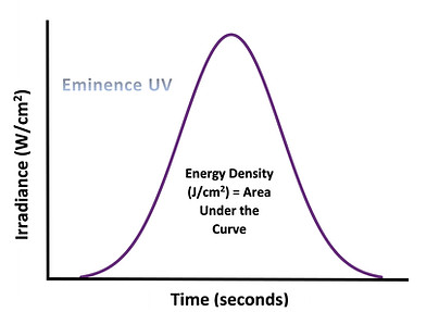
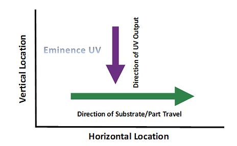

The first graph represents an irradiance profile for 1) a fixed lamp located in a vertical plane (y-axis) centered at the peak of the bell curve while a cure surface travels horizontally at a constant speed along the x-axis and 2) a fixed cure surface at the x-axis with a slightly offset lamp traveling horizontally and parallel to the cure surface at a constant speed. The bell shaped irradiance profile corresponds to the peak irradiance at a fixed location on the cure surface at each point in time during a dynamic pass. The second graph illustrates the direction of UV output for a fixed lamp with respect to a horizontally moving cure surface.
The greatest irradiance at the cure surface during a UV pass, represented by the peak of the bell curve, occurs when the center of the lamp and a point on the cure surface are vertically opposed. The irradiance at the cure surface increases as the cure surface approaches the lamp horizontally (perpendicular to the emitted UV rays) and falls off as the cure surface moves away. A faster travel speed would result in a narrower bell cure with respect to time. A slower travel speed would result in a wider bell cure with respect to time. A lamp with a greater irradiance would produce a bell cure that stretches taller along the y-axis. The greater the area under the curve, the greater the energy density, and typically the better the cure.
For a static On/Off application where the lamp and cure surface are fixed, the irradiance profile is a rectangle as opposed to a bell curve. Only in static installations where the cure surface is evenly exposed to UV and the emitting source instantly achieves the desired power output when switched ON or by opening a shutter mechanism, does a simple irradiance multiplied by time calculation yield the correct energy density.
Irradiance vs Energy Density
It is important to understand the difference between irradiance and energy density as both parameters along with spectral wavelength are critical aspects in achieving full cure. In distinguishing between the two, peak irradiance is the delivered power at an instant in time, and energy density is the total delivered energy over time.


An analogy used to illustrate the difference involves the baking of a cake in a typical kitchen oven. The oven temperature setting represents irradiance, and the heat delivered to the cake batter over time represents energy density. There is an optimal temperature setting (power) sustained over a precise period of time that results in a sufficient amount of heat transfer (energy) to the raw cake batter. Only the optimal combination produces the desired physical change of liquid cake batter into a properly baked and uniformly dense cake.
While minor adjustments up or down to temperature and time may still produce the desired cake consistency, turning the temperature up significantly will not bake the cake quicker and will most likely burn it. Conversely, decreasing the temperature by a considerable margin will also not yield a properly baked cake regardless of how long you leave the cake in the oven. The cake batter, just like a UV formulated material, has physical and chemical constraints in how it effectively absorbs energy.
In UV curing, there is both a minimum and maximum threshold of irradiance that is suitable for a given formulation. These limits represent the process window for irradiance. It is critical to stay within that process window. Delivering sufficient energy density while maintaining the irradiance process window will result in full cure for a given formulation. If cure is insufficient for a given light source emitting the correct irradiance, energy density can be increased by using a wider emitting source, adding one or more lamp heads in sequence, or slowing down the line speed. Remember, energy density is the irradiance delivered over exposure time. Extending the exposure time in either a dynamic or static installation will increase energy density and improve cure.
Nominal Power (W/cm or W/in)
Nominal power is the applied wattage of the power supply divided by the length of the lamp. Nominal power is a calculation. It is not a measurement. Nominal power is commonly used to specify the power output of conventional arc and microwave lamps (bubs and lamp heads) for purchase and use. Nominal power does not capture inefficiencies in the conversion of electrical power to UV light. It assumes that all available input power is converted to UV output, which is not the case.
While nominal power varies considerably by product, microwave lamps are available in nominal powers up to 600 Watts/inch (236 Watts/cm), and conventional arc lamps are available in nominal powers up to 800 Watts/inch (315 Watts/cm). A higher value is not always better as an inefficiently designed system would not necessarily convert more of the power to UV light. In fact, more may be going into infrared or visible output.
Nominal power is a practical and acceptable means of comparing arc and microwave systems, but it is not a relevant spec for comparing conventional lamps to LED sources since the ways the technologies generate UV output are so drastically different. While nominal power can be used to compare UV LED systems to each other, the UV LED industry has not adopted this specification for communication purposes and has relied solely on irradiance. That said, as long as you know the wattage supplied to the UV LED lamp head and the length of the lamp head, it is possible to calculate the nominal power for one UV LED curing source for comparison to other UV LED curing sources.
The following table is a representation of typical 450 mm (18 inch) lamps (mercury and LED). The tabulated values are not absolutes and will vary for the actual products being compared. The sole purpose of the table is to illustrate the fallacy in using nominal power to compare conventional lamps to LEDs. For the same length lamp, there is no correlation between LED and mercury lamps that allows the use of a mercury lamp's nominal power to determine a suitable LED equivalent. Nominal power for a mercury lamp provides no insight into the required LED wavelength, irradiance, energy density, and general ability to cure a formulation. LEDs are simply more efficient at converting electrical energy to UV output, concentrate all the converted energy into a relatively monochromatic band of UV (as opposed to spreading the output across several bands), generally result in a lower nominal power than mercury lamps, and require different chemistry.

Total Radiant Power (W or J/sec)
In general lighting, total radiant power or total luminous flux is the spatially integrated, phototypically weighted, total light output from an emitting source. It is the radiated energy emitted, reflected, transmitted, or received per unit time. It is a common measurement used for the purposes of emitting source calibration and comparison of emitting sources within UV, visible, and infrared bands. Total spectral flux (W/nm) goes a bit further and accounts for wavelength, and the total radiant power divided by the lamp electrical power is the luminous efficacy (lm/W) of the lamp.
Total radiant power is the most important parameter for non-directional, general lighting products. For directional lamps that employ reflectors and optics, intensity and beam angle are more important parameters. While total radiant power is commonly used in the development of Lambertian UV LED sources to quantify and compare output and efficiency, it is not typically employed by arc and microwave lamp manufacturers. Total radiant power of UV LED curing sources has not been commercially correlated to irradiance and energy density and, therefore, is not practically used outside of UV LED source development.
Process Window
Inks, coatings, and adhesives are formulated to react to a given UV LED output under a specific set of process conditions. For each application and formulation, there is a UV process window within which acceptable cure can be achieved. This window is not narrow, but there is an optimal set of wavelengths as well as a minimum and maximum irradiance and energy density combination that results in proper cure. Consistently operating within this window better ensures optimal line speed, a non-tacky surface, adequate adhesion, sufficient cure, minimal post cure migration, and product life among other desired performance criteria. Establishing and maintaining a UV process window for a given application is important for producing optimal yields and quality product over time.
The following graphic illustrates the process window for irradiance. Every formulation will have a minimum and maximum irradiance threshold in which cure can be achieved. A safety factor encompassing the risk of the user is then applied to the max and min. This may be 10, 15, 25% or possibly greater for higher value components. The operating or process window is then the working irradiance range within which quality parts can be repeatably produced. If adjustments cannot be made to keep the UV output within the working window, maintenance may be required such as changing the lamp (bulb), cleaning or replacing the reflector, cleaning the emitting window, replacing modules, replacing the magnetron or power supply, or going with a higher output emitter.

UV technology performs well when UV output is correctly matched to the needs of the application and paired with a suitably formulated ink, coating, or adhesive. Unfortunately, there is no universal UV system or process window that works equally well for all applications and all formulations. The UV solution and its output should be chosen for the chemistry, the plant or shop environment, the intended application, and the configuration and speed of the material handling system.
A major benefit of UV LED technology is that the discrete nature of LEDs allows for a much wider range of curing system designs that can better fit the needs of each unique application. This allows both form factor and UV output to be tailored to the respective markets and applications resulting in much more efficient and economical UV LED curing solutions compared to conventional curing technology.
Measurement is critical to ensuring a process window as there are numerous variables in a UV curing application. These variables can drift over time and are sometimes inadvertently, or intentionally, changed. All variables and their acceptable working range should be identified once acceptable cure is established. The variables should be periodically measured to ensure that the process remains in control. Should any instruments report readings outside of the working range, adjustments should be made.
The more common variables in UV curing applications include:
-
Distance and alignment of UV source from cure surface
-
Peak irradiance at a defined distance from UV source
-
Energy density required for acceptable cure
-
Machine speeds that yield the required energy density for a given source irradiance
Additional factors that should be noted and monitored include:
-
Changes in lamp (bulb) type or supplier
-
Surface energy
-
Use of pretreatment and the respective settings (flame, corona, plasma, wash, chemical treatment, etc.)
-
Viable substrates or part materials including grades, quality, and age
-
Distance of UV source from the point of formulation application / time lapse between formulation application and cure
-
Environmental conditions (temperature and humidity)
-
Formulation viscosity, temperature, batch, storage conditions, and age verses shelf-life
-
Formulation application settings (anilox, plates, screens, pads, rollers, nozzles, pressure, wear, etc.)
All variables will have a working range or process window. It is important to understand the upper and lower points at which failure occurs. The lower and upper limits that produce failure dictate the operating process window thresholds.
UV Meters
Overview
Instruments designed to measure and calculate UV output are called radiometers. Radiometers are helpful in establishing process windows as well as identifying gradual degradation in UV output, sudden equipment malfunctions, and unintended user changes to operating parameters. Radiometers report peak irradiance, energy density, or both. Some radiometers report a single reading over a defined broadband UV range. Others report separate values for one or multiple UVA, UVB, UVC, and UVV bands. Some meters report the highest irradiance value sampled over a period of time while others display a real time, dynamically changing irradiance value. Radiometers either display the latest recorded value which is erased right before the next use, or they are equipped to provide all the sampled data points for export to file. The exported data can then be viewed, analyzed, and plotted in Excel or other product software.
Irradiance readings reported by radiometers are relative values. In other words, all measured irradiance values are relative to the meter's factory calibrated UV reference source. Since commercial radiometers from different manufacturers do not necessarily use the same calibration source, the same wavelength filter(s), the same sensors, or the same sampling rates, there is always some deviation in measured values across meters. As a result, the same radiometer, calibrated per factory suggested calibration schedules, should be used for monitoring UV output for process control over time. In addition, any values used for documentation and communication purposes should reference the meter type along with serial number, calibration date, and procedure used for data collection.
Radiometers that calculate energy density do so by sampling irradiance many times per second over a period of time. Each irradiance sample point is multiplied by the sample time period in order to calculate a rectangular sliver of area under the irradiance profile. When the sampling is complete, all of the discrete areas are added together to approximate the total area under the sampled irradiance profile. A greater sampling rate (data points per second) produces more narrow and more numerous rectangular areas which ultimately yields a more accurate energy density calculation. The process is akin to doing mathematical integration by adding many small rectangles that lie under a curve. In fact, these instruments are sometimes referred to as integrating radiometers.

Broadband vs LED vs Spot Cure Meters
Meters specifically designed to measure broadband sources should be used with mercury arc and microwave lamps only. Meters specifically designed to measure a precise UV LED output (365, 385, 395, or 405 nm) or a wider UV LED range of outputs should be used with UV LED curing systems only. Meters specifically designed for spot cure systems should be used to monitor spot cure irradiance and light guide degradation only. Using the incorrect meter for the emitting source will result in erroneous and inconsistent readings. It should be noted that many UV LED pinning lamps often consist of a single row of LEDs (as opposed to a matrix of LEDs) as well as optics that columnate the UV output. Emitters of this style do not generally produce a physically wide enough beam profile to saturate the aperture of the radiometer, thus making it difficult for radiometers to accurately measure pinning lamps.
Radiometers contain band filters, sensors, and apertures that are uniquely designed for the specific type of emitting source (mercury, LED, or spot cure). Many UV LED and spot cure systems emit irradiance values that far exceed the maximum irradiance levels of conventional broadband meters. UV LED systems also concentrate UV output in areas of the spectrum that conventional meters never intended to measure. As a result, most UV LED output is not captured by broadband meters. This means that broadband meters typically under report UV output from UV LED curing systems.
External, Integrated, and Online Monitoring
Most radiometers are separate external devices and are not part of the UV curing system or OEM printer or coating line. External radiometers are typically engineered and sold separately from the total curing solution. They are generally designed to measure the UV curing system in an open access set-up and often aren't suited for use within large, high speed, closed chamber, or web manufacturing lines. External radiometers are also not designed for continuous UV exposure. The device will overheat in a short amount of time and prolonged, continuous UV exposure will ultimately damage the radiometer sensor. External radiometers are best suited for lab or production set-ups that either incorporate a flat bed conveyor that allows the radiometer to travel beneath the UV system or in set-ups where the lamp is easily accessible through a door or port in the shielding.
There has been growing interest in the need for UV monitoring that is integrated directly into the curing source. Some conventional and LED lamp manufacturers are just starting to offer integrated monitoring solutions; however, much of this technology is still relatively new and should be considered first generation. Many companies are actively working on integrated lamp monitoring which should result in steady improvements over the coming years. Some challenges include developing sensors designed for prolonged UV exposure, having to monitor the entire length of a UV source which can be anywhere from 75 mm to 2 meters, positioning sensors in internal locations that fail to capture the effects of dirty reflectors, optics, and emitting windows. In some cases, integrated monitoring may indicate a properly functioning lamp head; however, it's not the emitted output near the source that we really need to know, it's the UV output that reaches the cure surface across the entire width of the manufacturing line that counts.
Online monitoring has been around for a while. It allows users to continuously monitor and track a UV source in a production environment. Online monitoring is often used in applications where an external radiometer will not fit, where high value and/or high production speeds are used, and when it is not practical or easy to access each lamp (multi-lamp bank or lamp installations buried in equipment or installed at high elevations). As with external and integrated radiometers, the feedback is relative to a calibration source as well as the installation location of the device. While the meter may not record the UV output at the optimal location, it's purpose is to monitor changes in output with respect to its installation location over time. With online monitoring, smaller radiometers can be installed in a fixed location or automated to move throughout the press.
Radiometers - Puck Style
The most commonly used radiometers are referred to as pucks, primarily because the devices loosely resemble the shape of a hockey puck or disc. Puck style radiometers are available from various suppliers, are about 13 mm (1/2 inch) thick, and vary in diameter up to 150 to 225 mm (6 to 8 inches). Puck radiometers work best when used with flat bed conveyors where the UV source is mounted above the conveyor at a fixed distance. The radiometer is switched ON and passes beneath the light source while traveling on the conveyor belt. The following two images are puck radiometers from EIT. The first is a broadband, four channel meter. The second is a single channel 395 nm LED meter.


Radiometers - Wand Style
Wand style radiometers are typically designed to be hand held; although, they can be incorporated into a fixture that allows them to travel underneath a lamp head at a constant speed through use of a conveyor belt or x-y table. Most wand style radiometers only measure irradiance. They are meant to be a relatively quick check on irradiance provided the lamp head is easily accessible. Like all radiometers, wand styles are sensitive to heat and prolonged UV exposure. As a result, readings should be taken quickly. Increased stability and better performance during longer sampling periods can be achieved by mounting the wand in a liquid-cooled fixture. This is more commonly done in quality and development labs as opposed to production environments. In a production environment, the wand can be quickly moved along the length of the lamp to measure irradiance uniformity. The following single channel, dynamically reading, wand meter is provided by Gigahertz-Optik,

Radiometer - Spot Cure
Hand held radiometers and hand held radiometer attachments are available for measuring spot cure system irradiance. The devices monitor UV spot cure performance and light guide degradation. They are instrumental in optimizing light guide positioning and determining the optimal irradiance for curing various materials. The following spot cure radiometers are from EIT and Excelitas.


Measurement
Proper measurement of UV light sources is important in several ways. First, formulators and equipment suppliers use measurements when they develop new materials to create a specification, optimize it, and figure out the edges of the process window. Laboratory measurements become the benchmark for how to cure inks, coatings, and adhesives in manufacturing processes. Regular measurements are part of good process control to safeguard against production line defects and minimize scrap. Finally, when things go wrong, UV measurements provide a diagnostic tool to help isolate curing problems and get things back on track. Overall, measurements provide a common language and documented history for everybody involved in the process and are an essential tool that should be used in both development and production.
The values that affect cure are the irradiance and energy density at the cure surface for the respective wavelengths or lamp (bulb) types that drive the desired reaction. This is true for arc, microwave, LED, and spot cure systems. The curing system should be selected and adjusted if necessary to deliver the output that meets the requirements specified by the formulator at the cure surface for the desired production line speeds. It should be noted that radiometers contain sensors that are buried somewhere within the thickness of the meter. As a result, it is not possible to measure exactly at the cure surface since the sensor is generally located at a slight offset distance from where the planar surface of the meter is positioned. It is generally recommended that end users use the same meter as the UV source supplier or develop a new benchmark reference point for the meter being used. This is perfectly acceptable since all UV measurements are relative anyway, and one of the main purposes of measurement in both the lab and production is to monitor how irradiance and energy density change over time once proper cure is established. For an established curing process, it is not so much the magnitude of the measurement but whether it is consistent or changing over time. If it is changing, how much has it changed and how quickly.
While it can vary, arc and microwave lamps utilize reflectors that typically concentrate the UV energy at a focus that is 50 mm (2 inches) from the face of the lamp head. This is where the irradiance is greatest. Spot cure systems specify irradiance at the exit of the light guide. For LEDs, there is no generally accepted reference point. Some specify near the diodes, others at the emitting window, and others at an offset distance from the window. All measured values should reference the meter used and the conditions of measurement should be specified. Energy attenuates rapidly as you move away from the reference location. Not all spec sheets specify irradiance at varying distances, and energy density has a time component. As a result, it may be necessary to work closely with the UV system supplier for clarification on these values or measure yourself.
Whichever meter or meters you decide to use, it is of utmost importance to establish a measurement protocol that is precisely followed every time. Any changes in measurement procedures will yield measurements with zero correlation to previous readings. Measurements should be taken the same way each time. The meter should be oriented in the same direction and located at the same distance or distances. A good rule of thumb is to always measure three times and take the average of the values.
The following parameters affect all measurements.
-
Meter accuracy (typically +/-5 to 10%)
-
Meter repeatability (typically +/-2 to 5%)
-
Meter operating temperature
-
Meter sampling rate
-
Meter band filter range
-
Meter dynamic range
-
Meter orientation
-
Location of meter with respect to UV source
-
Speed meter is passed beneath UV source
-
Meter calibration UV source
-
Meter calibration date
Depending on the sampling rate, more accurate measurements can be achieved by using slower transfer speeds that allow more data points to be captured. The transfer speed is typically the conveyor belt for a puck radiometer or the speed at which a hand held meter is moved within the cure path. Since irradiance is reported as the peak value measured, it is independent of speed. This means that the irradiance measured at a slow belt speed is the same that the cure surface experiences at a faster production belt speed. Since energy density is scalable across greater speeds and multiple lamps, any measurements reported by the meter at a slow speed can be extrapolated for faster speeds or additional lamps. For example, baseline irradiance and energy density measurements taken at 10 mpm (33 fpm) can be extrapolated for faster speeds or multiple sources as shown in the following chart. Only the grey shaded values were measured. The rest of the energy density values for a single lamp were extrapolated using the following formula:
Energy Density 2 = Energy Density 1 * Speed 1 / Speed 2
Energy Density 2 = 1.446 Joules/cm2 * 10 mpm / Speed 2
The energy density for a second and third lamp located one after the other for a given press speed is simply a multiple of the energy density for a single lamp at that speed.

One major take-away from the chart is how quickly energy density decreases with increases in press speed. While many UV sources may cure fine at low press speeds, they simply do not emit sufficient energy to cure equally well at greater press speeds. If you only run at low speeds, a lower energy density lamp is sufficient; however, if you routinely run at press speeds of 150 mpm (500 fpm) or more, then you absolutely need a UV system with a higher energy density output. Multiple banks of lamps may even be necessary for speeds over 300 mpm (1,000 fpm).
One of the biggest differences between UV LED systems is the amount of energy density they emit. LED systems with the same peak irradiance often have dramatically different energy density values. Refer to UV LED Curing Sources for more information. By comparison, conventional arc and microwave lamps have less variation between systems. Another point that should be emphasized is that extrapolation is theoretical. In practice, it is often the case that adding a second lamp may not exactly double the line speed. It may only increase the speed by a factor of 1.7 to 1.9. As a result, a safety factor should always be considered when scaling a system from the lab to production.
Integrating or Ulbricht Sphere
Total radiant power is measured with an integrating sphere, also known as an Ulbricht sphere. The device consists of a hollow sphere where the inside surface is coated with a highly reflective material. The special material ensures full integration and homogenization of all emitted radiation that enters and bounces around the inside surface of the sphere. Integrating spheres are research and development tools. As they are rather large and bulky, they are not practical field measurements tools. The integrating sphere in the following photo is produced by Labsphere.

An integrating sphere contains various ports where emitting sources, research materials, and detectors can be placed. Light is directed into the sphere and reflects numerous times off the inside surface. It is ultimately measured via a detector port. Measurements are taken in 1 nm slices, and a mathematical computation is used to determine the total radiant power. Depending on the set-up, an integrating sphere can be used to measure total power due to emittance, transmittance, absorption, or reflectance with respect to various wavelengths.
Integrating spheres are available in various sizes to provide functionality for a wide range of applications. The size of the emitting source to be measured dictates the appropriate integrating sphere size. Larger sources require larger integrating spheres in order to minimize measurement errors. With larger spheres, sources can also be placed inside the sphere as opposed to mounting the source outside the sphere and directing the light through a port.
Conventional Arc and Microwave Measurement Sheet
When it comes to UV measurement, determine the optimal meter for the application, establish a protocol, measure early, measure often, and calibrate the radiometer per the recommended OEM schedule. The following test sheets can be used to record necessary information during trials and are available for download in both PDF and Excel spreadsheet formats.

